Chapter 5
Basic Volt Meter
When you start to make electronics circuits or if you try to fix a problem, you will need and require measuring tools. It is said that the success of any technician or engineer is based on his/hers ability to measure precisely and to figure out how those measurements effect or will work in the circuit.
To do this we use measuring tools or instruments. Without instruments a technician becomes blind, because these tools are like gateway windows that show you the operation and performance of electronic circuitry.
One of the most basic instruments/tools in electronics is your everyday, basic voltmeter. If you don't atleast have a voltmeter on your hobby or professional bench, then you are no technician.
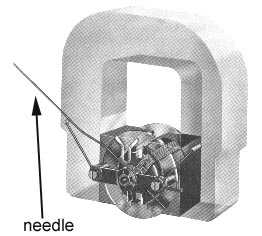
These days voltmeters are all digital, but I think it is important to understand how the old meter worked, and I am refering to the dial ones, that used a moving coil and magnets.
These were called the D'ARSONVAL meters, because they depend on the interaction of a moving magnetic coil which is in its self positioned inside another fixed magnetic field. There are volt meters for DC and AC.
When you introduce electrical current to the moving magnetic field, the one that the read dial is attached to, the current will produce a magnetic field around the conductor. So, when this current caring conductor is placed into a fixed magnetic field, these two magnetic fields will add together on one side and oppose on the other. Just like N and N will oppose and N and S will add.
Because of this, the moving coil conductor will move towards the weaker side when the current is introduced and the result will be that the arm will move with it and tell you the voltage. The coil is attached to a spring, and the current flowing will always make the arm move in the clockwise direction and against the tension of the spring.
Once the current is taken away from the meter, the spring pulls back the arm to read ZERO.
By arm, I am refering to the indicating needle of course.
Have you ever looked at one of these meters and wondered, hmmm, how do they determine about the reading on the scale, I mean how do they know if to measure 2 volts the indicating needle has to move a certain distance from 0 ?
By full scale deflection I am refering to the indicating needle moving from 0 to as far as it can go on the chart, as far as the spring that is pulling back on it will allow it to move away in the opposite direction without blowing up.
This is done by knowing several things before accurate meter movement can be printed.
What is the DC ohmic resistance of the moving coil, because as we have learned from previous sections, all wire has resistance per foot, right ?
What current is required in the moving coil to make it or cause it to move a full scale deflection of the indicating meter needle
and what voltage applied across the moving coil will cause a full scale deflection to flow in coil
Anyways, the actual meter hardware is rated at a certain deflection ratio, and if you apply more energy then the meter can handle, you will blow it. That is why resistors are placed into them in various sizes and values so that you can select the voltage range that you will be measuring for, ever seen that on your meter ? well now you know.
This is called MULTIPLIER RESISTOR circuit. With a basic hardware meter that can only handle max. maybe 1 volt, you can expand to measure 5 volts, 50 volts and so on if you use the right multiplier resistor settings.
Go to the library to learn about that : )
Now lets talk about sensitivity of meters and circuit loading. Sensitivity of a voltmeter can be used to determine how much if any the meter will load a circuit when it is used to measure voltage. What I mean by this is the following.
If you are using a volt meter in a 5 volt circuit, and the volt meter is not of high quality, circuit loading will occur, where part of the voltage is transferred into the meter and incorrect reading is been taken. Very few people know this, but it is important to use high quality meters, the higher the meter resistance the better, and high resistance meters will barely give off any bad reading, circuit loading will be very low.
For how this works get a book. And the formula for finding out the meter sensitivity is OHMS PER VOLT.
Anyways I am going to skip a little bit to cover the rest of the chapter and in the future I will fill in some parts back with more information. So here we go.
How A/C Voltage is measured with a meter ?
A/C if you have forgotten is alternating current, and before a meter will tell you the correct reading, this A/C voltage must be rectified. What do I mean ? Rectification is when you change back A/C waves into pulsating direct or D/C waves.
I will tell you much more about rectification in later chapters, but will briefly fly across it here.
In simple meters this process of rectification can be simply accomplished by using a DIODE. A diode is an electrical component that allows current to flow in only one direction, it is unidirectional.
Because the A/C wave flows in one direction for some time and then in the other, the DIODE will only permit one direction to flow through it thereby cutting the A/C current basically in half.
This what I just described to you is called HALF WAVE rectification output, FULL WAVE rectification is where the waves that are under 0 and above 0, are simply neatly stacked above one side of the line, because they have to go only in one direction.
So in the previous chapters when I drew the line and there were waves above +0 and below -0, well you just draw the above waves normally, but the negative waves are drawn also in positive territory or on one side. It looks like when you are moving slowly and jumping up and down, but you aren't falling throught the floor into negative territory and back above the floor : ) I will draw a picture soon and scan it, if you are visually/imagination impaired.
What type of meters are there ?
There are the manual armature meters, the old types and there are the newer digital multimeters. Multi, means a meter with more then one type of meter, like a volt meter, amp meter, ohm meter and so on.
The Oscilloscope
What the hell is it ? This instrument is used to measure signals waves of voltages. It is used by more advanced hobbies or professionals like technicians and engineers.
Here is a picture.
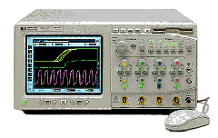
A good oscilloscope costs mucho money and even an entry level one will set you by more then couple of hundred dollars. So learn about electronics first before wasting money on that. These devices can get pretty fancy and very! expensive.
There are special models for students and if you look in the right place, maybe you can get a discount.
End of Chapter 5.
Chapter 6
What is INDUCTANCE ?
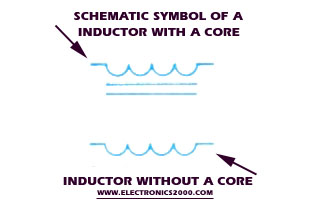
Inductance is what opposes change in current in a circuit. In electronics the letter L represents inductance. Inductors are devices which oppose any change in current regardless in what direction. Some inductors are primarily used in A/C circuits, like for example in power transformers, etc...
A coil that has wire wound around it will produce a magnetic field, if you let electric current flow through it, right ? If you are confused about what a coil is, it's very simple, take some wire, wind it around your finger or a pencil and then remove it and you got a coil, the more layers you wind on top of each other the more layers you get and the more powerful of a coil you can make. If you put a core inside, that's something that the coil is wound around all the time, like a pencil or a nail, that is exactly what a core is. This is how you make electromagnets:
Here is a simple example of how a A/C inductor works. (Picture coming soon to help to illustrate the example.) Imagine a simple circuit, 6 volt A/C, and to it you connect a inductor, which can be as simple as a coil, with or without a core and nothing else, if you let the current run through the circuit, this is what happens; As the current flows, remember current is AMPS and current and volts are proportional to each other, most of the time if one rises so will the other. So, as the current flows through the circuit, a magnetic field will induce in the coil. This field will start from 0 and then will expand to it's fullest value or flux density.
As this flux field moves outward, it cuts across the wires that make up the core or otherwise called windings of the coil. This will induce a voltage in the INDUCTOR coil and this voltage will OPPOSE the source voltage coming from the A/C source (whatever that might be). As it opposes the source voltage it will also oppose the rise in AMPS or current and kinda act as a resistor at the same time. And if you add a simple 6 volt lamp to our circuit and do this experiment in A/C and then the same in D/C, you will notice that in D/C the lamp will glow bright and in A/C it won't, it will glow dim because the inductor is constantly opposing the rise in current and opposing the voltage, although some voltage does get through, that's why it glows dimly.
The induced voltage inside of the COIL is called CEMF or counterelectromotive force. If you now let's say lower the source voltage to 3 volts A/C, the amps lower in the circuit, if there is less power in the circuit, the magnetic field previously induced can't sustain it's maximum value, so it will start to drop down, as it goes lower the decreasing magnetic field in the inductor will once again induce a voltage against the coil windings as it goes down to a lower value and because of this will tend to hold it's original current value. The opposite is also true.
Motors are inductive devices, even tho we don't think of them as such and don't use them in modern electronics to restrict current flow in one direction only.
And what is a DIODE ?
A diode is a two element unilateral conductor. UNILATERAL means that the diode has two parts to it or connections, "anode" and a "cathode" but the electric current will only flow in only one direction through this component.
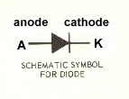
To understand this process 100% you have to understand the semiconductor theory, which is what I am going to cover next.
Refer to Chapter 1 for Conductor, semiconductor and insulator basics. Remember that semiconductors are human made elements, they are designed on purpose to semi-conduct.
The impurities that are mixed into the making of the semiconductor make this possible.
You have to understand VALENCE and how this works in semiconductors. The number of electrons in the outer shell minus the full permissible complement for that shell, determines the VALENCE of the atom. That is why the outer shell in the atom is called the Valence Shell. The amount of electrons in this VALENCE shell will determine how well this atom can carry free electrons or not.
An atom for example where the VALENCE shell that has a full complement of electrons in the shell, will easily gain electrons to complete its shell. Once this electron is gained a very large amount of energy is required to free it. So atoms with less electrons in the VALENCE shell will lose these electrons much easier.
The PERIODIC TABLE OF THE ELEMENTS, Any Chemistry Lab should have one or book, displays under what group the atom is registered under depending on how many electrons are in the VALENCE shell. The higher number of complimented electrons that reside in the VALENCE shell, the harder it is to break those type of materials for conduction and a much greater amount of energy is required to make them conduct.
Most inorganic materials are of crystalline structure, that is how the atoms are arranged to make them like that. Crystals can be arranged in either random fashion or lattice formation.
If you want to understand this 100% first read up on Basic Atomic structure and how that works. Then get familiar with how semiconductors are made, the type of different dopants that are used to make this material and what the combined mixture becomes.
But to summarize there are two types of crystals used in electronics. There is a N type and a P type. Again to understand the following you need to understand the basics : )
N type crystals or semi-conductors conduct by adding a PENTAVALENT dopants, these are atoms with 5 electrons in the valence shells. Once doped by mixing the dopants into pure crystal, the mix becomes an N type semi-conductor and it conducts by the extra electron.
It is called a N type crystal because the majority of carriers that transfer the electrical energy between the atoms are electrons. P type crystals conduct by the opposite, by HOLE conduction where the majority are holes to be filled.
If you are confused about what a HOLE is, that is because you have failed to read the basics and you will not understand this and you will NEVER understand how basic components such as a diode operates or a transistor.
Getting back to N type, in it are holes too, but they are few compared to the majority and for this are called MINORITY carriers which do carry an electric current, but the amount is very little and insignificant.
The dopants that is used on a N type crystal is called a DONOR IMPURITY, where in the P type it is called a ACCEPTOR IMPURITY.
The dopants that are used in the P type crystals or mix are called TRIVALENTS and some of them are indium, gallium, and boron. On the other hand in the N type the most common ones are phosphorus, arsenic, bismuth, antimony to mention the common ones.
To get back to P type, the valence shell bond once mixed will result in a shortage to complete the covalent bonding structure. This will leave off a HOLE and electricity is transferred by the HOLES. Majority carriers are HOLE and minority are electrons.
The crystal will end up N or P depending on the type of semiconductor material used with a mix of a dopants. This will all depend on both materials and the end mix result of the covalent bonding structure where the atoms meet in the outer shells. Excess will result in a free electron that will pass and exchange from atom to atom and shortage will result in HOLES, where electrons can be passed by when electric current is introduced into the semiconductor.
If you are confused : ) learn physics basics and some chemistry wouldn't hurt. Otherwise you will never understand this : )
Now to answer the original question of the DIODE, it basically has two parts to it a N and P type crystal, 1/2 and 1/2 like this : )
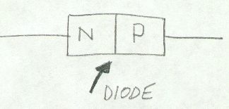
A diode will resist electric current in the opposite direction and only allow it to run in the current direction. Diodes must be correctly connected. One end will have a + and the other -. If you connect it incorrectly, the plastic shielding will blow out and you will only be left with the wires. As a matter of fact a mini explosion will happen and if you are not wearing protective eye wear, those small pieces of plastic can flow right into your eye and leave you blind in one eye or cause serious damage. So wear eye protection if you are a newbie to this and aren't sure.
You can't replace an eye yet, but you can easily replace a diode.
The material in the diode as you can see from the above picture is separated into two sections, N type and P type crystals. Then the N type is alloyed with a metal base. Keep in mind that N and P type can also be determined by the rate growth at the time the crystal is grown. There are different ways of making N and P type, some of these methods include diffusion or the rate growth that I briefly mentioned.
Diffusion is more preferred in the manufacturing industry. At the separation or the junction where N and P are touching each other, electrons in the N type are attracted to the HOLES awaiting in the P type, this is also true where P is attracted to N. REMEMBER!, N works by electron, P by HOLES, electrons go into the HOLES to fill them : )
In any case, this attraction area is called the DEPLETION area or it is sometimes referred to as the transition or space charge region.
Because of this exchange, the area of exchange becomes void of carriers, whether they might be holes or electrons. Because of this attraction exchange a electrical potential develops and this potential is called a BARRIER. If you hook up a battery where the + lead is connected to the N type side, (note that: N = -, P = +), As the N electrons jump over to the P side, they or that area becomes positive and P holes becomes negative in that BARRIER area, picture coming up soon.
So if you hook up a battery + to - N, and battery - terminal to + end of diode, the depletion area or the barrier area increases in width and the source voltage join together to prevent current carriers from crossing over the junction where the N and P join. In order for the diode to conduct and let the electricity through you need to connect the - terminal of the diode to the negative terminal of the battery, - to - and + to +.
If you connect - to + and + to-, it will block. P type in semiconductors means Positive and N type means Negative just so you know.
How does it work by conduction ?
If you connect - to - and + to + of the diode terminals to the battery terminals then you get what is called FORWARD BIAS, blocking is called REVERSE BIAS.
In Forward Bias, where the gate is opened and the diode conducts and let the electric current go through, this happens:
The electrons from the P side are attracted to the + terminal of the battery, once they leave the P side to the battery + terminal a HOLE is created, and this hole is filled up on the N side, because the electrons are attracted to the positive side of the P crystal. The N side gets it's energy from the negative terminal of the battery. So the electricity flows from the negative terminal to the N junction, electrons are attracted in the P junction to the + terminal of the battery and when a whole is created N side fills it up and this process repeats over and over, and this is how a diode conducts.
Hope I did not loose you. There are all kinds of diodes used for all kinds of different purposes : )
Next I will cover the TRANSFORMER!