Basics of Electronics, Part IV
I don't know, I think that the subject of generators is so important, because it deals with A/C and FREQUENCY, that I might dedicate a whole chapter for it, will see.
So here we go.
One of very few but important people from the past and now in history books that you should know about is and was named, MICHAEL FARADAY. He lived during the early part of the 19th Century, and he is mostly remembered for his work on DYNAMO's. If you don't know what a DYNAMO is, don't worry, I will teach you about this later.
Anyways, he was one of the people who has spent an excessive amount of time working with electricity and magnetism and studding the relationship between them. He reasoned that if Electricity could be used to create electromagnets with, why not then reverse the process and use electromagnets to produce electricity with.
Sounds reasonable to me : )
So, through his work and a major time effort devoted to this subject, Michael over time has discovered Magnetic Induction, I did explain what this is in Chapter 3.
Basically what his work lead to was to use MOTORS to produce electricity with. If you take a conductor and move it inside a magnetic field, this will produce a voltage, more correctly, the voltage will be induced in the conductor.
Either the conductor can be moved or the magnetic field can be moved around the conductor to achieve the same effect.
If you take a small motor, you know, one of those hobby motors, you will see magnets around a moving COIL of wound wire that moves. When you introduce an electric current to the motor, it will start to move. If you remove the ES, Electric Source and then place the MOTOR over water so that the moving current of the water can make the bearings of the motor move, you can create electricity.
Here you are using, the moving force of the water, which is in it self a type of energy, then you transfer it into mechanical energy inside the MOTOR and that translates the mechanical energy into electrical energy that move down the wire and into the electric plant.
This is how Electric DAMS work, but a lot more complicated.
Anyways, Mr. FARADAY lived from (1791-1867) and came from England. Hmm, if it wasn't for him, you would still be reading books under candle light :), and in order to honor this great in it's own way inventor, we named the unit of capacitance after his last name, FARAD.
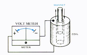
As the COIL is moving around the SOUTH and NORTH POLE MAGNETS, it will produce DEFLECTION of current. If you connect a VOLT meter, one of those ones with hand arms, you will observe the meter deflecting from 0 to positive, back to 0 and into negative territory.
Relative motion must be present in the magnet or in the MOTOR, or current can not be produced. This is how those WIND Propellers generate Electricity that you sometimes see mentioned on TV in the deserts of California and Arizona.
This should give you some hints about why A/C current Alternates. Are you getting the idea right about now ? Great.
Anyways, here is an inside view of a typical MOTOR, doesn't matter what kind for now.
I am not an ARTIST, but try to imagine this.
The magnets reside around the moving coil of the motor. How much VOLTAGE can be produced from a typical type of MOTOR or DYNAMO depend on the following factors:
The SPEED at which the moving coil conductor cuts the magnetic field through.
The STRENGTH of the magnetic field around the coil.
The LENGTH or number of turns around the COIL.
The ANGLE at which the conductor cuts the FLUX field.
So if the speed at which the conductor cuts through increases, that induces on the electrons within the conductor and result in a greater voltage output from the generators.
The big generators in Electric Power plants are huge and a lot of energy is required to make them move. This is because the polarity of the fields opposes the movement of the conductor that cuts through them. We need actual mechanical energy to move the generators, thus why we use water or atomic power to move the generators because a lot of energy is needed to move them. So now you know how generators convert mechanical power into electrical. Without mechanical power, electricity would not be possible.
Here is a LAW to memorize for you that provides the scientific explanation for this subject.
"The polarity of an induced EMF-electron moving force, is such that it sets up a current, the magnetic field of which always opposes the change in the existing magnetic fields."
Now here I will explain why A/C Voltage moves in one direction for a while and then changes polarity and goes in a different direction. This is tied to the generators that create the electricity at the electric plant.
The conductor that moves inside the generator is called an armature, at the end you have types of brushes, like in DC motors, these pass over the induced voltage to the two output terminals and then the electricity is let out of the generator and into some type of circuit where it is further processed.
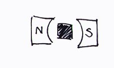
First to induce the maximum voltage out of a generator, the ARMATURE must cut the FLUX in the proper degree angle, and for maximum this is at 90 deg.
As the armature is moving around inside the generator, the wire loops are cutting at right angles. In one quarter of a revolution, the armature will be moving parallel to the field, which in this case no voltage will be induced, but in yet another quarter of a full revolution, the armature will be cutting at 90 deg. again, So both sides of the armature are moving through the FLUX field but opposite of each other. The result is, an induced voltage opposite in polarity and the current or AMPS will flow in the opposite direction. Thus why the A/C current moves like waves. This wave by the way has a name, it is called a SINE wave.
This is called the Alternating Current or A/C Sine wave. The major difference between DC and AC is that AC is continually changing amplitude and polarity as such I just explained.
A CYCLE is described as this: The cycle of the wave starts at zero, it rises to a maximum of the positive polarity, or one polarity, drops to zero, goes exactly the same in the opposite direction or negative polarity, and then returns to zero. This constitutes one CYCLE. 60Hz, moves exactly like this 60 times per second.
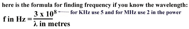
Frequency I explained in Chapter 3. Now a PERIOD of a SINE wave is simple, even if the explanation sounds complicated. Period has the letter of T assigned in electronics. The formula is
T = 1 / f in Hz
The explanation is as follows. If you are trying to find out the PERIOD of a 60Hz wave, the typical wave at 115VAC, here is how you do it. The time in seconds for the durations of one CYCLE is PERIOD.
So 60Hz wave has a period of 1/60 sec. or 0.016666 sec. This is the PERIOD time for each cycle from 60Hz.
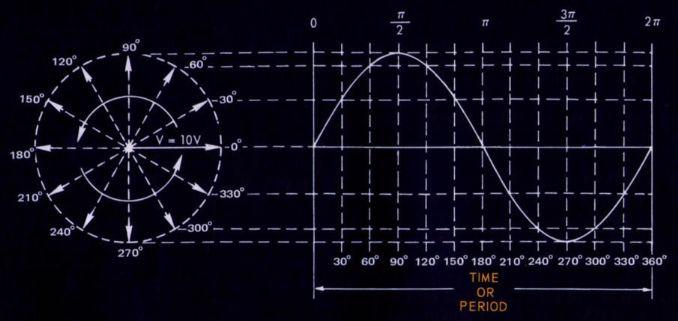
Here is an example of the SINE Wave chart, so that you can get a better idea of how it looks like.
The circle with the arrows represent the armature that moves around the generator. It starts at 0 deg. and moves around one full cycles or a full revolution of 360 deg.
And based on where the armature is located inside the generator the SINE wave will be different, and again that is why it alternates.
You can find out what the PERIOD answer is for all frequencies like even in radio, by using that above example. Here is something else, try this. A radio station operates (only an example) at 99.9 KHz. Right off the bat, the K stands for thousand, so this in fact is 99,900 Hz, so that means that the frequency wave is moving at 99,900 cycles per second.
So, T = 1 / 99,900 = 0.00001 sec. So each individual CYCLE of each of the individual waves that make up the frequency is only 0.00001 sec. and if you take 0.00001 and multiply by 99,900 you get 1 or the value of 99,900 cycles per second for our frequency. The 1 stands for all the single CYCLES that make up the 99,900 freq. for a duration of one second.
The higher the frequency, the shorter the wave length. Here is how that works.
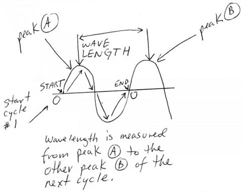
What's PEAK VALUE ? To simply put it, it is the maximum amplitude of a wave in either positive or negative direction starting from zero. A PEAK TO PEAK VALUE is the value of the frequency wave from the maximum positive peak of the wave to the maximum peak on the negative side or vice verse. Another way to explain it is the value from both peaks, which represents two times the peak value.
What's WAVELENGTH ? The length of a wave is measured from the peak of one cycle (from the top, see picture above), to the corresponding peak of the next value. If you start having more cycles per second, less waves fit into the one second, so the WAVELENGTH becomes shorter and shorter. If you reduce the frequency, the wavelength becomes wider and wider.
The Greek letter (lambda) :
![]()
is the letter in electronics that represents WAVELENGTH.
Frequency waves travel at light speed which just happens to be about 186,000 miles per second, that's:
 meters per second or again 186,000 miles per
second, which is the same thing.
meters per second or again 186,000 miles per
second, which is the same thing.
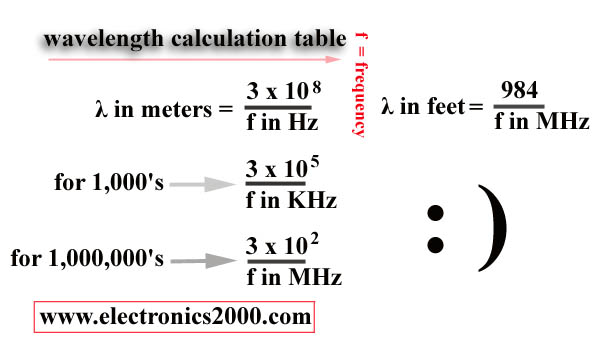
If you know the wavelength, you can find out the frequency and vice verse.
Example is as follows: What is the wavelength of a 10 KHz wave ?
First you look what you are solving for, so we are dealing with K - thousands of HERTz. So we would use a power of 5 on the 10. So 3 times 10 to the Power of 5, divided by 10. That will give you 30,000 metres or meters.
Example is as follows: What is the frequency of a 90 meter wave ?
3 x 10 to the power 2 divided by 90 = 3.333 Mhz, to see if you are right, simply reverse the formula and solve for meters or.
3 x 10 to the power of 2, divided by 3.333 = 90 meters. So it works : ) You can reverse the same process for the first example. If you are confused, don't worry, it takes getting used to, read it a couple of times : )
Keep in mind that metre is not spelled wrong when refering to meters, it is the same thing, metres and meters = same. Metre is british. 1 metre is 39.37 inches.
I found this really good site that explains a lot of the Radio related and wireless terms and what they mean. For example, do you know what RF means ? no ? then please link here and you'll learn.
RF/Microwave Terminology - Glossary of Wireless, RF and Microwave Terms
Another interesting value to know is called the Effective Value, this value compares the A/C to D/C equivalent value of an A/C wave in order to produce the same power in a resistive load compared to a steady D/C SINE wave.
Some other terms you should be familiar with are Amplitude, which measures something similar to magnitude. The bigger the magnitude or something, the greater the size, or in this case the value reached by the SINE wave or waveform.
Modulation; the variation of a property that makes up the electromagnetic waves or signals such as it's frequency or phase.
Ok that's it about A/C Waves. There are many books dedicated to this subjects and the formulas can become quite complicated and lengthy, so if this interests you, do the research on your own. Let's move on to the subject of GENERATORS and some basic types that are out there.
I am going to explain several things here: SINGLE-PHASE Generators, Two-Phase, Three-Phase and Alternators.
To understand what I am about to explain to you, you must get some kind of an idea, a painted picture of what I am talking about, so here is a side view, of the inside from a typical generator.
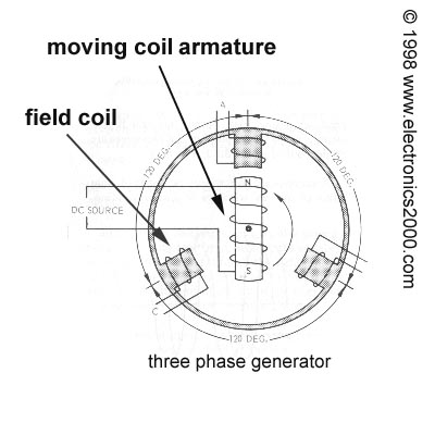
The above image is of an three phase generator, because the three field coils are spaced at 120 deg. apart, and each coil will produce its own sine wave. These three out of phase voltages can be easily put together or used singularly. A two-phase generator would have four field coils, and each coil is separated by 90 deg. apart., One might guess why then isn't it called a four phase generator ? because only two sine waves are produced. While there are four field coils, you have to remember that the armature will touch two fields at the same time, N end and S end, then it rotates and moves above the other two. So it produces only two sine waves. The Single phase one has two field coils, but so what, the armature produces only one single sine wave.
If you are having a hard time understanding this, don't worry about it. Get a book with lots of pictures and it should be able to show you what I mean. Solid state electronics don't use generators anyways, and I am only covering the basics here. But no matter how boring this might sound, you must understand this, because this will teach you a lot about the basics of rectifying and what a rectifier is and how it works on later.
A quick note about a/c generators and alternators. Both of these devices have a disadvantage. What ? While in operation these devices produce high voltages/currents and then they are transferred to the rotating armature which connects to the external circuit by the form of sliding contacts also known as slip rings or brushes.
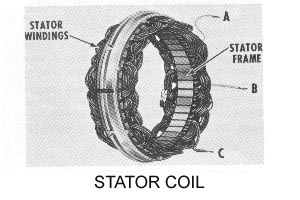
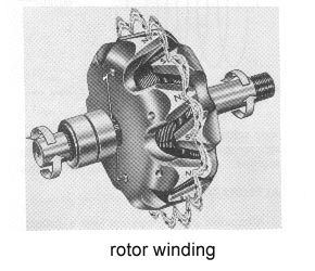
Because of high voltage, these contacts can and do spark and burning can and does result with time. Therefore engineers decided to induce the voltages in fixed coils called STATOR WINDINGS and revolve the magnetic field around the ROTOR WINDINGS, this way there is less friction. Because of this, the alternator or generator, becomes also a DYNAMO.
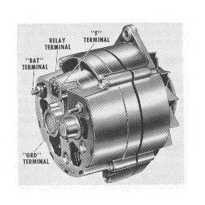
Below are pictures of these two items that are put together into a typical automobile alternator/generator : )
I let you guess what this is : )
Because of this setup, it is only necessary to supply enough electricity to the rotor to make the generator, generate electricity. The rotor kicks in and starts the magnetic field up and that makes it move. This generates the electricity, that's why they are called generators. The movement is transferred from the timing belt : ) another example of mechanical energy into electrical energy.
That's as much as I feel like writing about this subject, pick up a book and read more if you want to : )